
Introduction
The purpose of the PTT switching isolator is to provide isolation and protection to equipment in your shack when transmitting.
Over the years I have had to replace a number of front-end devices that were damaged by harmonics and induced voltages in secondary devices when transmitting at high power levels on HF and VHF. In particular, 2m front ends when transmitting on the 17m band and 23cm front ends when transmitting on the 2M band.
This unit can accept up to three PTT inputs (HF/VHF transceiver or amplifier) which operate two relays with two pole change over contacts providing four isolated switching outputs.
The outputs can be used to switch RF relays, mute inputs, PTT inputs etc, on auxiliary equipment requiring protection during ORO transmit.
Description
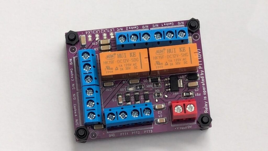
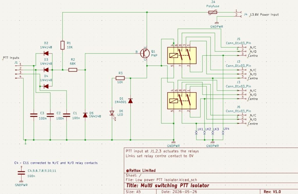
The design of the unit is fairly simple, if you refer to the schematic you can see a PTT signal at any one of the three inputs activates the relays and illuminates a red led to confirm operation.
The function of the board is to isolate and protect equipment in your shack. It achieves this in the following ways –
1 – ensures no high voltages or other signals can interfere or damage your transceiver PTT output,
2 – enables you to apply an isolated PTT signal to auxiliary equipment,
3 – by setting the link/s to provide 0V switching to auxiliary equipment.
The unit activates when 0v is applied to any of the PTT inputs (OR function).
The PTT inputs are diode isolated so you can connect up to three PTT lines.
All the unit’s switched inputs and outputs are decoupled to earth to avoid stray RF or voltage transients interfering with operation of the unit.
There are four links on the PCB that can be bridged using solder (see the Links on the schematic and image above) these set the centre contacts to 0v delivering this through the respective change over contacts
N.B. Using the links sets the contacts to 0v. In most cases this is a common ground for the whole of your shack so not an issue but if complete isolation is required the links should be left un-soldered. They are then completely isolated make and break contacts.
Each change over contact can handle a maximum 1A 125V AC, 2A 30V DC
The unit is designed to work from between 11v to 14v dc (13.8v suggested). The minimum current required to switch the relay is 34 milliamps.
The unit includes a 2amp thermal fuse, if a short develops on the supply, removing the fault the thermal fuse will reset after which you can re-applying the voltage
Schematic
Other typical uses for this product are:
1 – keying a legacy amplifier that draws more power the PTT output on your transceiver can handle,
2 – providing simple PTT distribution on integrated microwave systems,
3 – activating the mute function on independent HF receivers,
4 – integration of positive and negative earth equipment.
N.B. if you need to switch higher currents I provide another product capable of switching 7 amps at 13.8v which can be used to switch off a VHF transceiver, pre-amps and low power amplifiers.
All units are functionally tested to ensure they work correctly before release indicated by an attached QC sticker
If you are interested in this project, please contact me through this website.
73 Rex G8UBJ