
Following the development of some initial firmware there have been a number of modifications to the Quansheng UV-K5 range of transceivers.
Without modification firmware exists to operate from 18Mhz up to 1.3Mhz however the transceiver is reasonably deaf below 4M and above 70cm and transmit isn’t advised because harmonics can be greater than the fundamental!
KD8CEC created some very nice firmware which combined with an additional PCB containing a chip SI4732 enables full band HF reception using AM USB LSB and CW.
His original work and links to the software can be found here:
http://www.hamskey.com/2024/04/introduction-to-uv-k5-hf-05-fullband.html
And here is a link to the hardware modification here:
http://www.hamskey.com/2024/02/uv-k5s-hf-full-band-reception-lsb-usb.html
Based on this a number of HF PCBs were manufactured mainly by Chinese companies so I thought I would make my own.
MK1 HF PCB
The circuit is fairly simple but the dimensions were fairly critical. Some time on Sprint Layout and I had a prototype which after testing worked quite well.
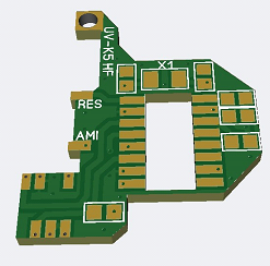
I modified a few transceivers with this original PCB but the audio output on HF was a bit low.
MK2 HF PCB
Suppliers had recognised this and included an op-amp in their boards to boost the audio. This seemed a little overkill so I experimented with a single stage NPN amplifier set with a gain of 10db. I wasn’t sure how well this would work and rather than fitting the chip in a cut out I had to use the space for routing power and audio making the finished unit slightly thicker.
When the prototypes arrived they worked first time and I was delighted. The audio level was much better and easy to increase where it overcame external noise when taken portable.

MK3 HF PCB
Over time some manufacturers moved onto another variant of the HF PCB so it could be connected to a separate antenna port.
Up for a challenge I made a final product which included a uf.l connector. This routed by coax to an SMA fitted in place of the LED on top of the transceiver. This was a fairly tricky PCB to design as I had to avoid components on the main PCB and add the uFL connector without fouling the internal speaker
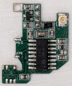
I also included a link to the original antenna port so this PCB can be used with a single or dual antenna ports
Mechanically this is a trickier build than the single port. The case of the radio has to be drilled to accept an SMA connector and routing the coax without fouling the case is tricky.
I can now make both types of transceiver
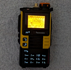
If you’re interested in obtaining one, please get in touch via the Contact me link
General Specifications
HF receive up to 30MHz.
2m and 70cm SSB (DSB Transmit).
It also covers air band, 6m, SHF etc receive.
Using HF on the UV-K5
Switch on the radio using the volume knob.
Default is 2m/70cm RX TX.
You can go into the menu and alter the mode to SSB on these frequencies.
In addition, there are more bands available including 23cm RX. Use the function band button to select these bands.
To activate HF receive press and hold the “0 FM” button.
This will put you into AM receive.
To activate SSB press and hold the “F Lock key” (bottom right).
Pressing the “F Lock key” key will now cycle through modes (USB CW and LSB).
Use the Menu button to step through the parameters where you can change (HF Band, Pre-amp Bandwidth, BFO) Once selected use the buttons on the left of the transceiver to cycle through the parameter you have selected.
Keyboard Shortcuts
BFO – In SSB/CW press the 1 or 4 keys to adjust the bfo in 20hz steps.
Direct frequency entry 150KHz to 30 MHz – Press 2 or 3 Keys then key in your HF frequency.
Tuning step change – */Scan Key.
Display band plan – 0/FM key -> More -> Exit.
Press the EXIT button to return to VHF/UHF.
There are tutorials on YouTube which give further guidance.